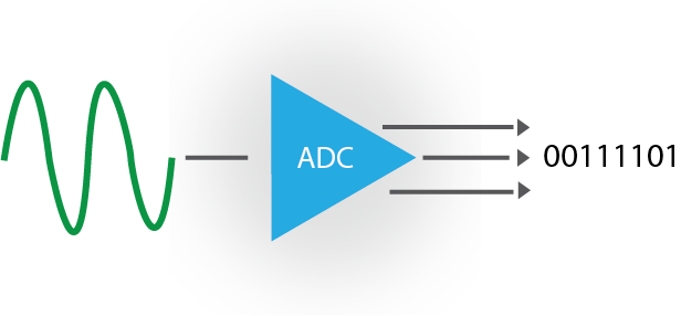

The digital data available at this instant is given as an output through the output register. The generated digital data is converted to an analog signal by the DAC, and then compared to the current analog signal and the reference voltage. Upon receiving the signal, the control unit of the ADC will give a command to the successive approximation register, which starts generating the digital signal by the successive approximation method. Refer to the datasheet for timing diagrams. Students are encouraged to use SPI modules to interface to the LTC1661. While bit-banging is usually less efficient, it can be easier to set up and use. For this tutorial, we will bit-bang the DAC using three bits from PORT2 of the MSP430. An ADC performs this conversion by some form of. Interfacing to a Digital to Analog Convertor with the MSP430. In more practical terms, an ADC converts an analog input, such as a microphone collecting sound, into a digital signal. The conversion process is initiated by an analog signal entering the ADC at Vin. Analog-to-digital converters, abbreviated as ADCs, work to convert analog (continuous, infinitely variable) signals to digital (discrete-time, discrete-amplitude) signals. Note 1: A ‘y’ is used with MUXA and MUXB control bits to specify the S&H channel numbers (y. The ADC result is available in four different numerical formats (see Figure 16-14). The DAC is a digital to analog converter, Vin is the analog input pin, S/H is the sample and hold, and COMP is the comparator. Analog-to-Digital Converter (ADC) Analog-to-Digital Converter (ADC) 16 For devices without DMA, the ADC module is connected to a 16-word result buffer.

The clock CLK provides the sampling rate, SAR is the successive approximation register, EOC is an output to the processor to indicate the current sample is complete, Vref is either the 5V supply, or an external voltage reference. Figure 1: Successive approximation analog to digital converter


 0 kommentar(er)
